TR Self Clinch Nut installation
The TR Self Clinch Nut can be installed into a pre-punched or pre-drilled hole using a press capable of a squeezing action, causing the parent material to flow into the specially designed under head configuration offering a load bearing and torque resistant joint.

Ensure the correct spigot length has been selected for sheet thickness being used. Select the appropriate hole size from the table below for the bush size required. Punch the hole diameter into the sheet.
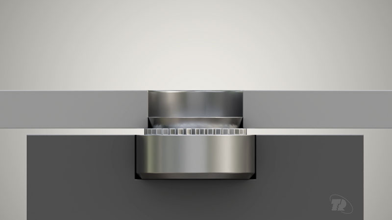
Place the nut spigot end up into the hole on the anvil, so that sheet rests on the serrations. Ensure both sheet and nut are aligned along the same axis. If the sheet is not seated ‘square’ on the nut, the joint will be imperfect and mating threads will misalign.
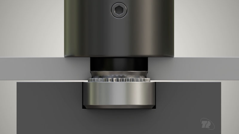
Using a punch, apply only sufficient pressure to ‘squeeze’ the nut serrations into the parent sheet.
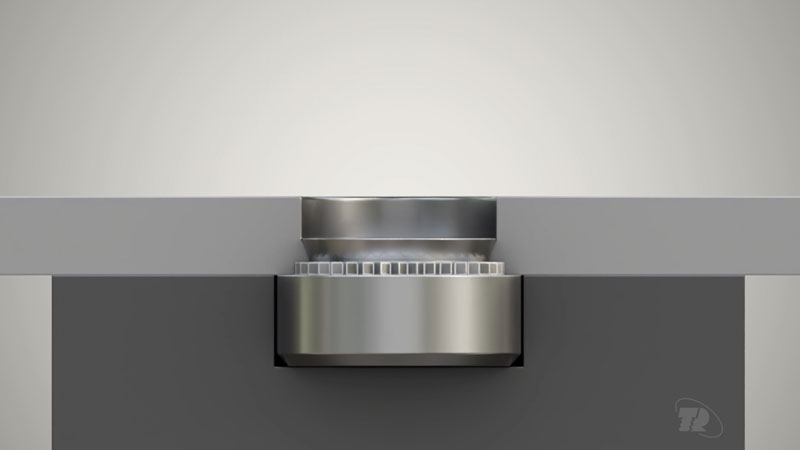
The serrations if properly installed will provide torsional (rotational) resistance. After installation the spigot joint should be flush with the sheet.
Can be installed sheet on nut or nut on sheet, for ease of application.
Installation animation
Using the table below with reference to the specific size of the Clinch Nut, select the correct hole size for the installation of the fastener.
For the best dimensional accuracy and therefore performance, TR recommends that all holes in the sheet metal application be punched.
To install the fastener into the punched hole a profiled punch is required. Note it is essential that the recommended hole tolerances be observed.
Hole sizes - metric (mm)
| Thread and pitch | M2 | M2.5 | M3 | M3alt | M3.5 | ||||||||||
|---|---|---|---|---|---|---|---|---|---|---|---|---|---|---|---|
| Code | 0 | -1 | -2 | 0 | -1 | -2 | 0 | -1 | -2 | 0 | -1 | -2 | 0 | -1 | -2 |
| Minimum rec sheet thickness | 0.8 | 1 | 1.4 | 0.8 | 1 | 1.4 | 0.8 | 1 | 1.4 | 0.8 | 1 | 1.4 | 0.8 | 1 | 1.4 |
| Hole size +0.08 -0.00 | 4.25 | 4.25 | 4.25 | 4.75 | 4.75 | ||||||||||
| Minimum distance to edge of sheet | 4.8 | 4.8 | 4.8 | 5.6 | 5.6 | ||||||||||
| Thread and pitch | M4 | M5 | M6 | M8 | M10 | |||||||
|---|---|---|---|---|---|---|---|---|---|---|---|---|
| Code | 0 | -1 | -2 | 0 | -1 | -2 | -1 | -2 | -1 | -2 | -1 | -2 |
| Minimum rec sheet thickness | 0.8 | 1 | 1.4 | 0.8 | 1 | 1.4 | 1.4 | 2.3 | 1.4 | 2.3 | 2.3 | 3.1 |
| Hole size +0.08 -0.00 | 5.4 | 6.4 | 8.75 | 10.5 | 14 | |||||||
| Minimum distance to edge of sheet | 6.9 | 7.1 | 8.6 | 9.7 | 13.55 | |||||||
Hole sizes - inches
| Thread and pitch | #2-56 | #4-40 | #6-32 | ||||||||
|---|---|---|---|---|---|---|---|---|---|---|---|
| Code | 0 | -1 | -2 | 0 | -1 | -2 | -3 | 0 | -1 | -2 | -3 |
| Minimum rec sheet thickness | .032" | .040" | .056" | .032" | .040" | .056" | .091" | .032" | .040" | .056" | .091" |
| Hole size +0.08 -0.00 | .166" | .166" | .188" | ||||||||
| Minimum distance to edge of sheet | .19" | .19" | .22" | ||||||||
| Thread and pitch | #8-32 | #10-24 & 10-32 | #12-24 | ||||||||
|---|---|---|---|---|---|---|---|---|---|---|---|
| Code | 0 | -1 | -2 | -3 | 0 | -1 | -2 | -3 | -1 | -2 | -3 |
| Minimum rec sheet thickness | .032" | .040" | .056" | .091" | .032" | .040" | .056" | .091" | .040" | .056" | .091" |
| Hole size +0.08 -0.00 | .213" | .250" | .277" | ||||||||
| Minimum distance to edge of sheet | .27" | .28" | .31" | ||||||||
| Thread and pitch | #1/4-20 | #5/16-18 | #3/8-16 | ||||||
|---|---|---|---|---|---|---|---|---|---|
| Code | -1 | -2 | -3 | -1 | -2 | -3 | -1 | -2 | -3 |
| Minimum rec sheet thickness | .056" | .091" | .125" | .056" | .091" | .125" | .091" | .125" | .250" |
| Hole size +0.08 -0.00 | .344" | .413" | .500" | ||||||
| Minimum distance to edge of sheet | .34" | .38" | .44" | ||||||
Tooling - standard

Tooling - hard stainless

| Punch dimensions | |||||
|---|---|---|---|---|---|
 |
Thread size | A mm +/- 0.05 | P mm +/- 0.03 | R mm Max. | R1 mm + 0.13 |
| M3 | 6.48 | 1.42 | 0.25 | 0.13 | |
| M4 | 8.05 | 1.93 | 0.25 | 0.13 | |
| M5 | 8.84 | 1.93 | 0.25 | 0.13 | |
| Anvil dimensions | |||||
 |
Thread size | A1 mm +/- 0.05 | B mm nominal | P1 mm + 0.03 | R2 mm Max. |
| M3 | 5.05 | 6.63 | 0.23 | 0.08 | |
| M4 | 6.17 | 7.75 | 0.23 | 0.08 | |
| M5 | 7.34 | 8.89 | 0.23 | 0.08 | |